News, Updates and Other Minutiae
September 2023 Long time between drinks, but not much happening on the tech front at the moment. Added another couple of rants to the rant page.
January 2023 Updated the AD9833 VFO code to use a 12F1840.
December 2022 Added rant about todays useless (internet) search engines.
November 2022 NEW Project An AD9833 Based Simple VFO. FT101ZD VFO project updated.
October 2022 A replacement internal DDS VFO for FT101Z/ZD rigs. Because the worlds postage system has gone totally bonkers and it is not possible to send a small pcb anywhere except at extreme cost, I am slowly making available the option to purchase pcb's from Pcbway. First up is the Simple DDS VFO 2017 project pcb. Others will be added over time. Noise Canceller kits available again- see Noise Canceller page.
Privacy Policy uploaded. GPDR and all that stuff In accordance with various bits of legislation around the world, either currently in force, about to come into force or proposed, you will now find that annoying "We use cookies" notice at the top of this website. The full Privacy Policy is available at the Privacy Policy link in the footer at the bottom of the page. (If you don't know what GPDR is, Google it. Real scary shit for ANYBODY with a web presence.)
DX160 Mods
Mods I have made to my DX160
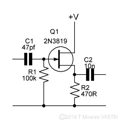
While waiting for some parts to arrive to continue on with the DDS signal generator, I thought I might as well do some mods to my DX160 receiver. While the DX160 has a nice dial with smooth operation, it is not easy to determine exactly what frequency you are on. It also does not have an audio out socket to enable recording of anything received. The first mod was to provide an output to drive a frequency meter. On the 'net, there are several sources of information for fitting a frequency meter. Most revolve around either tapping off from the local oscillator output or at the mixer with a 68pf cap. I tried this, but connecting or disconnecting the frequency meter would shift the local oscillator frequency somewhat. Not really the most ideal situation. My solution was to fit a FET buffer stage. The local oscillator frequency, now, does not change at all when connecting or disconeccting the frequency meter. This is the circuit I used, nice and simple.
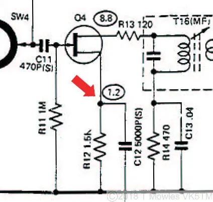
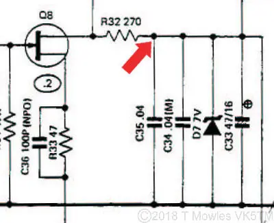
This was connected to the top of R12, which is the mixer point in the DX160, as shown by the red arrow in the schematic fragment below. Power for the FET buffer was taken from the local oscillator's stabilised 7v supply (next schematic fragment below).
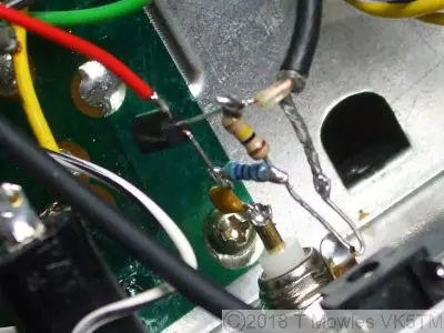
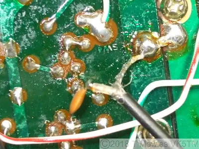
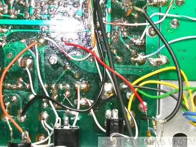
Here are some pics of the mods, first, FET buffer (built dead bug style), second, mixer tap off point and last, an overall shot of the area showing the buffer power tap off point.
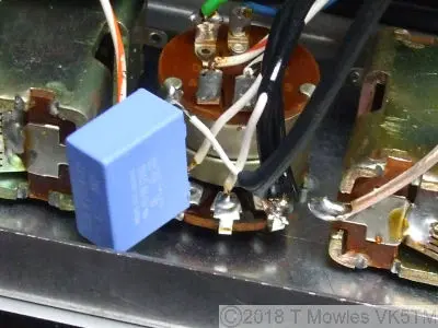
Next mod is a simple audio tap off. All it is is a 0.1uF cap connected to the top of the volume control and a piece of coax to a socket on the back panel. The cap in the picture is an 'X2' rated cap, used not for it's ratings, but because that was the closest at hand at the time.
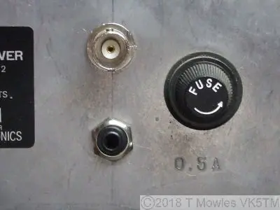
To accomodate easy connection and disconnection of the frequency meter and to connect an audio recorder, a BNC socket and 1/8th inch mono jack socket were installed on the back panel.
The 'purists' will go 'but you're destroying the resale value doing that'. Guess what? I don't care. The DX160 is not a collectable, they are reasonably plentiful and can be bought for $50 on average (2012). Besides, I intend to keep it until I fall off my perch anyway, so that will be someone else's problem. Having got the easy connections via the rear panel, I didn't really want to have a seperate power supply for the frequency meter. So, mod number three. There is a three pin sockect on the back to enable the DX160 to be powered from 12V. The pins are in a 'Y' arrangement, with the one at the tail of the 'Y' being ground or negative. At the top of the 'Y', both pins were connected together to form the positive connection, so I seperated them and connected a wire from one of the pins to a point after the main regulator. If you go back three pictures, you will see the orange wire I installed. NOTE: do not connect or disconnect anything to this with the DX160 turned on. I've already blown one fuse doing that. The lights will stay on, but nothing else works.
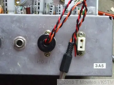
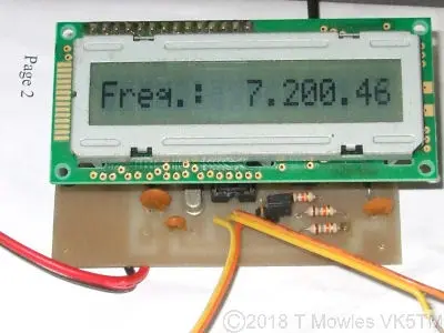
The orange/black twisted pair are power out (approx 9V) and the red/black twisted pair without a connector on is 12V power in (diode protected for reverse polarity). I haven't done any measurements, but I doubt this power out connection will support a frequency meter with a backlight. Extra modifications to the power supply of the DX160 would be required for that. Finally, here is a shot of a frequency meter connected and working. This one is a design of IK3OIL (search the net by his callsign for info). I have to find a box to fit it into, but it works marvelously.
AD9850?
On a side note, I have seen comments in various places regarding substituting an AD9850 DDS module for the local oscillator and connecting the rotary encoder to the existing tuning knob. While in theory it would give you a nice, stable local oscillator signal, trying to implement it is going to bring a whole world of pain. Firstly, the tuning knob not only tunes the local oscillator, but also the preselector and 1st RF stage. Secondly, you would need some way to index the rotary encoder so that it knows where it (and the software) is in relation to the dial markings. Probably not impossible, but it is going to need a whole lot of interconnecting electronics and engineering to make it work.
DX160 Service Manual
I have made a download available of the service manual. Please note that there are two versions out there on the 'net. One for the early version of the DX160 (like mine) and another for the later version. The main difference between the two is in the audio stage. The two schematic files below are for the 1st & 2nd edition respectively and have been redrawn by me so are nice clean clear copies - if you find any errors, please let me know so I can correct them.
Downloads (Right click and 'Save as..' or what ever is required by your browser)
DX160 Service Manual
DX160-1st_ed_sch.pdf Note this is the schematic for the First Edition of the DX160
DX160-2nd_ed_sch.pdf Note this is the schematic for the Second Edition of the DX160 - units manufactured after April 20 1975.
