News, Updates and Other Minutiae
August 2025 UR5WHK has created another version of the AD9833 project with a 128 X 32 OLED display. You can find it under the Gallery menu - it is on the same page as the MAX7219 version.
July 2025 UR5WHK has created an updated version of the AD9833 project which now includes a MAX7219 based LED display. Code updated 10 July 2025. Code updated again 15 July 2025. You can find it under the Gallery menu.
March 2025 In something of a "Seniors Moment", I forgot to update the homebrew menu and this section relating to a project I did late 2024. That project is an update of one from the RSGB Radcom magazine of Sept 1999 - 'Turn Your Dip Meter into a Signal Generator'. Presented here as 'Grid Dip Meter (GDO) Add on' under the Homebrew menu.
November 2024 Phillipe F6ETI has done some serious testing on the Noise Canceller and shown it works up to 72MHz and is usable with some loss at 145MHz. Links to his website with photo's, video's and description of the testing on the Noise Canceller page.
Privacy Policy uploaded. GPDR and all that stuff In accordance with various bits of legislation around the world, either currently in force, about to come into force or proposed, you will now find that annoying "We use cookies" notice at the top of this website. The full Privacy Policy is available at the Privacy Policy link in the footer at the bottom of the page. (If you don't know what GPDR is, Google it. Real scary shit for ANYBODY with a web presence.)
August 2025 - a version with a 128 x 32 OLED display added, See further down the page.
UR5WHK AD9833 DDS VFO & MAX7219 Display
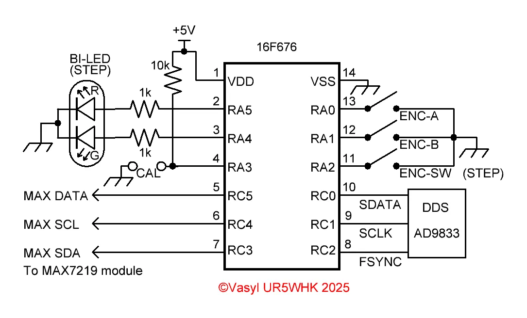
A version of the VK5TM AD9833 DDS based VFO with a MAX7219 LED display and 16F676 PIC .
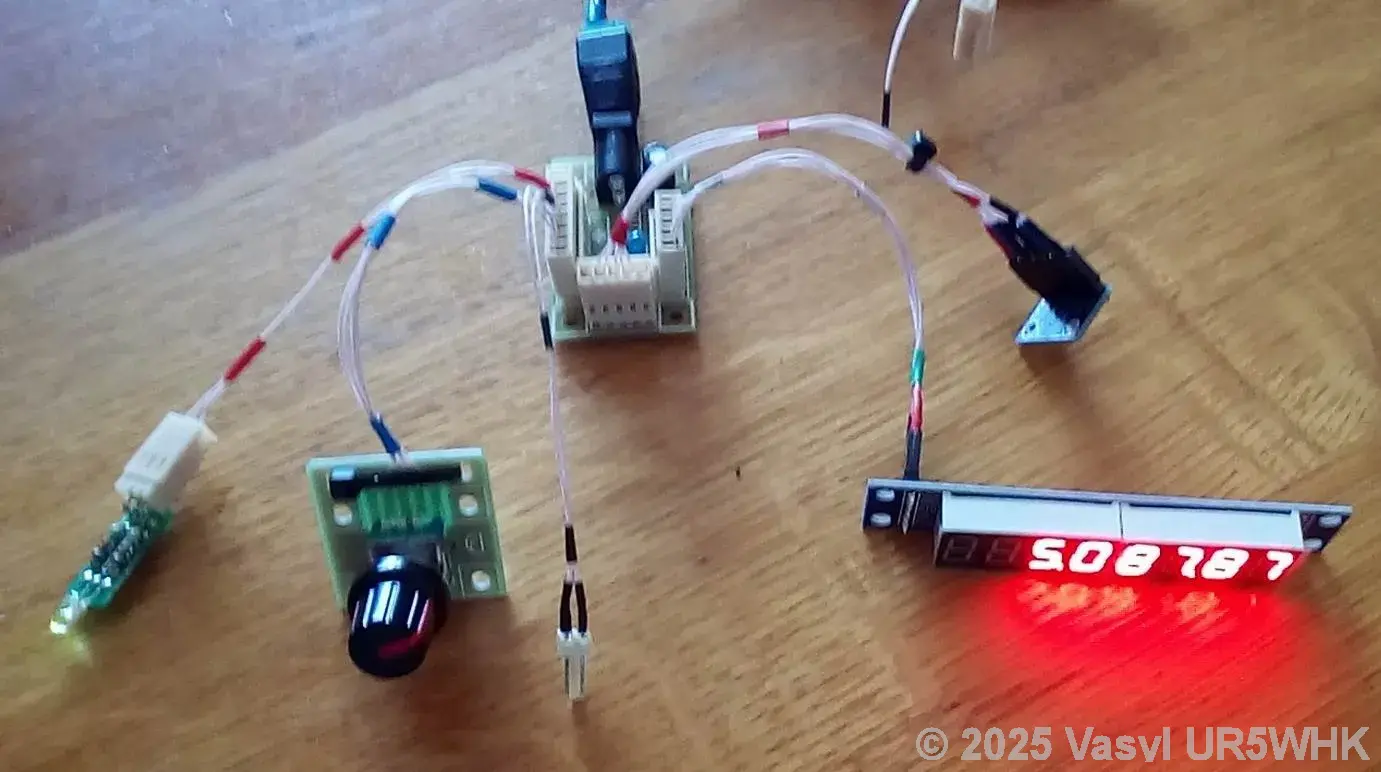
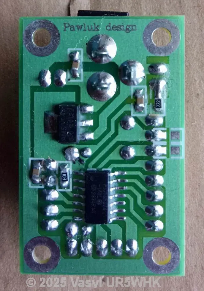
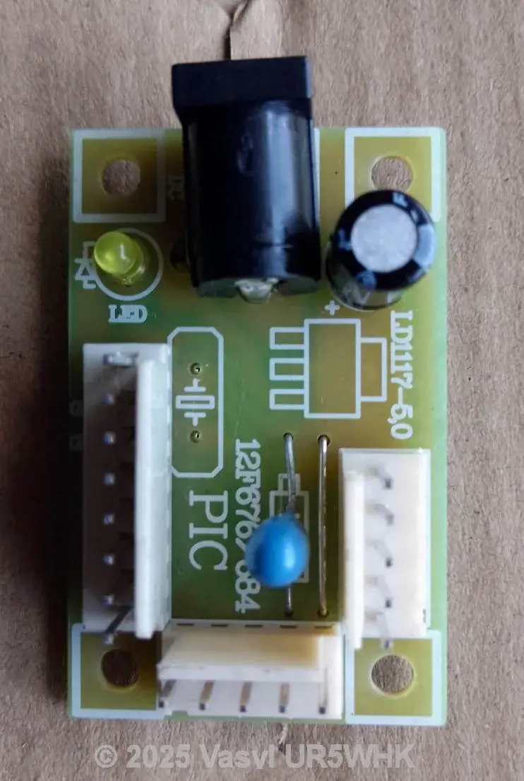
Vasyl UR5WHK has created an updated version of my AD9833 VFO project and has kindly given his permission for the project to be published on my website. This project is an update of my AD9833 VFO with the addition of a MAX7219 LED display module for the frequency and the LED step size is now indicated on a bi-colour LED, so the extra step size add-on electronics are not needed. To accomodate these changes, Vasyl has moved the code (available to download below) over to a 16F676 14 pin PIC. All the rest of the functions are the same as the original AD9833 project so I won't repeat all those details here. I have redrawn Vasyl's hand drawn schematic and the remaining photo's are of his build. There should be enough information for anyone to build their own copy, but you will need to design your own pcb for it or build it on strip board or Manhattan style or even dead bug style. Circuit wise, you will note the abscense of capacitors on the encoder inputs - debouncing is handled in the code. The default frequency span is 5-5.5MHz and the step sizes as indicated on the Bi-colour LED as follows: 10Hz LED will be Green, 1kHZ Green & Red and for 10kHz Red - and before anyone goes Red & Green mix to Brown, in the real world yes (supposedly), but in the LED world what you get is the two colours, Red & Green, illuminted side by side. You could substitute 2 seperate LED's for the bi-polar one, which would make it easier to see the Red/Green lit combination. Also note that the maximum frequency available can be set to 12MHz but I probably wouldn't top much more than 10MHz.
Code Updates
Just a quick word on the code updates. Vasyl has been refining the code to make it more compact and sort a couple of minor niggles, (mainly encoder related stuff) and now all the encoder and Step button routines are inside the interrupt routine. Also, in Vasyl's own words "There is still enough space left in the ROM to represent the actual reception or transmission frequency (not VFO ), taking into account the IF frequency." - at this point in time, that will be up to you, the builder, to add the code for.
Click any of the pictures below for a larger view. Click again to close.
Downloads
These files are provided free for personal use ONLY. I retain copyright on all works published on this website (unless otherwise specified). These files, or any derivative of them, may NOT be used in any commercial or profit making enterprise of any kind.
(Right click and 'Save as..' or what ever is required by your browser) Code updated to V1.3 15 July 2025 - Vasyl says this will be the last update (maybe). F676_AD9833_VFO_MAX7219_V1-3.asm The ASM file for the VFO. Default VFO range 5 - 5.5MHz. F676_AD9833_VFO_MAX7219_V1-3.HEX AD9833 VFO hex file. Here's a copy of the above code modified for use in a 16F1824. F1824_AD9833_VFO_MAX7219_V1-3.asm The ASM file for the VFO. Default VFO range 5 - 5.5MHz. F1824_AD9833_VFO_MAX7219_V1-3.HEX AD9833 VFO hex file.
UR5WHK AD9833 DDS VFO & 128 x 32 OLED Display
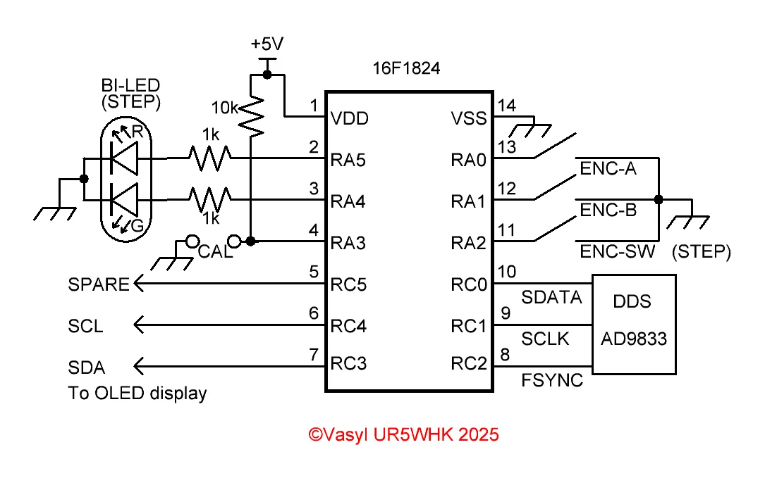
A version of the VK5TM AD9833 DDS based VFO with a 128 x 32 OLED display and 16F1824 PIC .
Vasyl UR5WHK has also created a version of the AD9833 project using one of those small 128 x 32 pixel OLED displays. In his version, he used a 16F676 and since I didn't have any of those on hand, I have ported the code to a 16F1824. Note that this is still a 'work in progess' as far as the code is concerned (the posted version below is fully functional). As above, the comments about the operational function is mostly the same as the original project, so won't be repeated here. The main difference code wise is that the encoder routine has been moved inside the Interrupt handler. Circuit wise, you will note the abscense of capacitors on the encoder inputs - debouncing is handled in the code. Also, the 10k resistor from pin 4 isn't strictly needed now as internal pull-ups have been enabled and how the Calibrate function is entered has been modified (there is also no need for the calibration reset function).
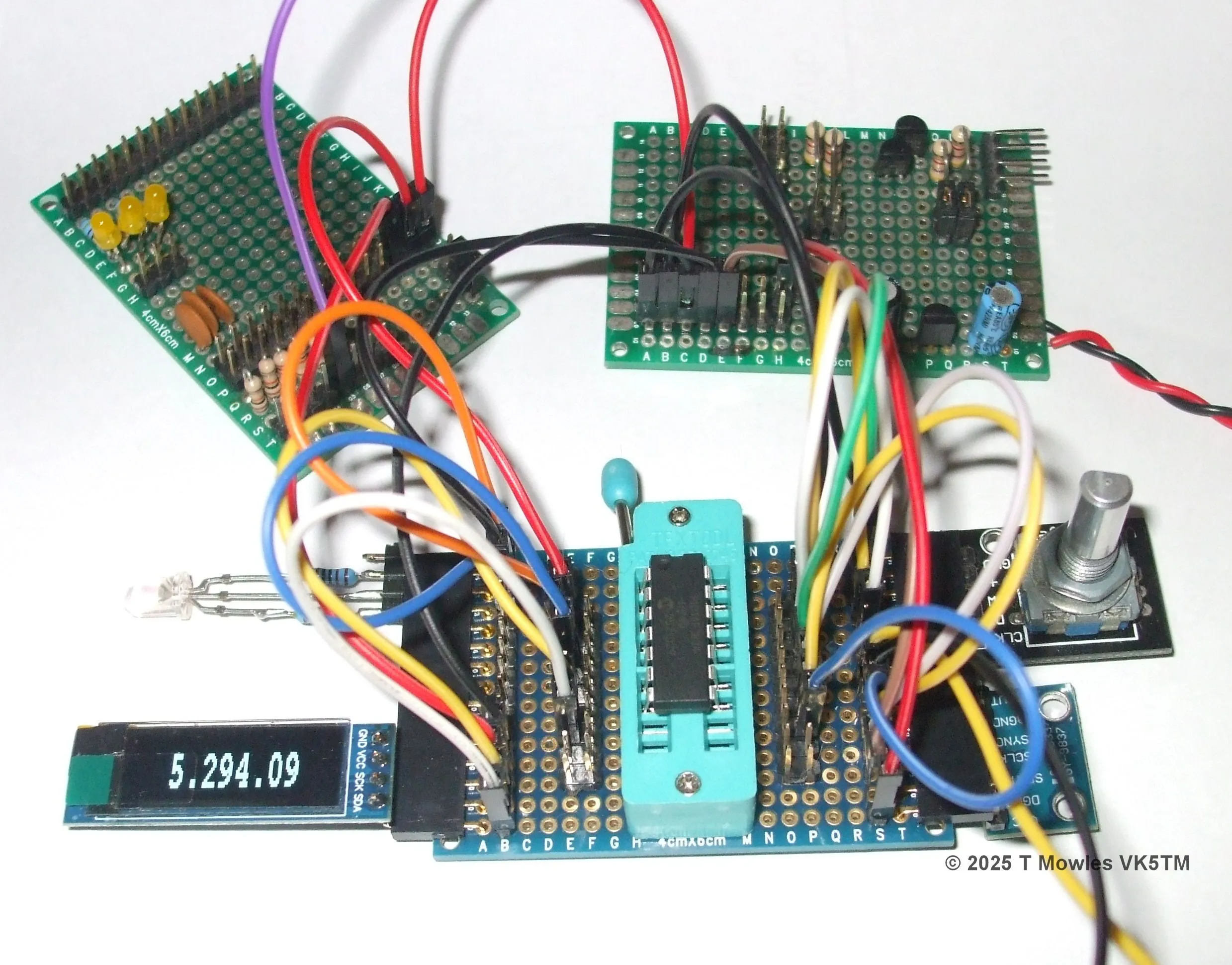
And here is my messy prototype lash-up of the project on the workbench. Note that the 1Hz digit is not displayed (but can be if you want it) as step sizes are 10Hz, 1kHz and 10kHz. The LED is lit, it just doesn't show in the photo.
Downloads
These files are provided free for personal use ONLY. I retain copyright on all works published on this website (unless otherwise specified). These files, or any derivative of them, may NOT be used in any commercial or profit making enterprise of any kind.
(Right click and 'Save as..' or what ever is required by your browser). F1824_AD9833_VFO_SSD1306.asm The ASM file for the VFO. Default VFO range 5 - 5.5MHz. F1824_AD9833_VFO_SSD1306.HEX AD9833 VFO hex file.
