News, Updates and Other Minutiae
August 2025 UR5WHK has created another version of the AD9833 project with a 128 X 32 OLED display. You can find it under the Gallery menu - it is on the same page as the MAX7219 version.
July 2025 UR5WHK has created an updated version of the AD9833 project which now includes a MAX7219 based LED display. Code updated 10 July 2025. Code updated again 15 July 2025. You can find it under the Gallery menu.
March 2025 In something of a "Seniors Moment", I forgot to update the homebrew menu and this section relating to a project I did late 2024. That project is an update of one from the RSGB Radcom magazine of Sept 1999 - 'Turn Your Dip Meter into a Signal Generator'. Presented here as 'Grid Dip Meter (GDO) Add on' under the Homebrew menu.
November 2024 Phillipe F6ETI has done some serious testing on the Noise Canceller and shown it works up to 72MHz and is usable with some loss at 145MHz. Links to his website with photo's, video's and description of the testing on the Noise Canceller page.
Privacy Policy uploaded. GPDR and all that stuff In accordance with various bits of legislation around the world, either currently in force, about to come into force or proposed, you will now find that annoying "We use cookies" notice at the top of this website. The full Privacy Policy is available at the Privacy Policy link in the footer at the bottom of the page. (If you don't know what GPDR is, Google it. Real scary shit for ANYBODY with a web presence.)
PCB's for this project can be ordered by clicking the PCBway pic ->  At the Checkout, make sure to scroll down the page and select your preferred shipping option otherwise the most expensive option is automatically selected.
Software updated April 2021.
Philips PM5326 mod sofware added November 2021 - updated April 2022
At the Checkout, make sure to scroll down the page and select your preferred shipping option otherwise the most expensive option is automatically selected.
Software updated April 2021.
Philips PM5326 mod sofware added November 2021 - updated April 2022
Simple DDS VFO - 2017 Update
A Simple DDS based VFO using an 8-pin PIC.
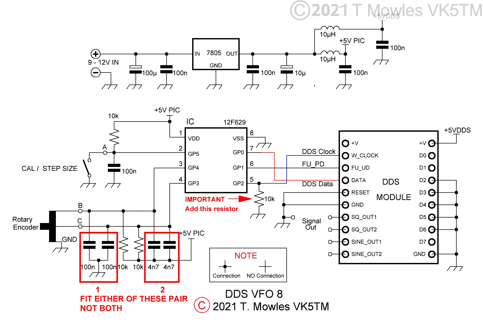
It is a VFO that can be used just as an ordinary transistor/fet VFO would be. This has been kept as simple as, any buffering, amplification or filtering is left up to you to build to suit your purposes. Yes, I have been fiddling again. The changes are - the inputs used for the Encoder and Calibration/Step switch have changed and a rearranging of some of the components on the pcb, plus, using a push button (or encoder push button), 3 step sizes of 10Hz, 1kHz and 10kHz are available. I swapped the inputs around as I need a port line not associated with the encoder that can be either an input or output for an add-on that indicates the current step size via LEDs. Note that to use the original software (or any of the modified versions I supplied prior to this update) with this pcb, fit the 100n capacitors marked as 1 on the schematic below and connect the encoder to inputs 'A' & 'B' and the Cal/Step switch to 'C'. Do not fit the capacitors marked as 2.
If you have one of the 3.3v modules, all that needs to be done is to replace the 7805 with a 3.3v regulator. The PIC will happily run at 3.3v and it doesn't control anything but the DDS module, so no other interfacing problems.
A note about the two sets of capacitors marked '1' & '2' - with the cheap mechanical encoders I have been using, I found that having the capacitors in parallel to the 10k resistors (marked '2' on the diagram) resulted in a much better waveform from the encoder. Other, better quality encoders may be different, so on this version of the pcb, I have given the option of the more traditional arrangement for the capacitors (those at '1') as well. You can decide which ones you want to install. Update May 2025 Some feedback re the value of the caps on the encoder inputs as shown in the schematic above is that it gives improper operation of the encoder in some cases. In one reported case, reducing the capacitor value shown for option 1 from 100n to 4.7nF gave good encoder operation. If you are having a problem with the operation of the encoder, try adjusting the value of the capacitors to smaller values such as 4.7nF for option 1 or 1nF for option 2.
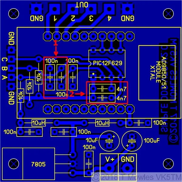
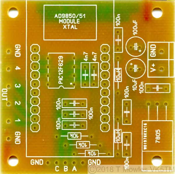
The pcb is only 2 inches (50.8mm) square. You can use either the AD9850 Module or the same format AD9851 module.
Software
There have been a few cases of errors compiling files and it is caused by using an older version of MPlab. I use version 8.92 (which is the last of the old MPlab versions) and the problem relates to the 'include' file and the Config defines of those older versions. Specifically the FOSC_INTRCIO definition of the later version - change it to INTRC_OSC_NOCLKOUT for earlier versions of MPlab. A few words about the software. You will need to input the values of and recompile the software for your required VFO frequency: Limit - The upper limit frequency you want the VFO to reach. Limit_Low - The lower limit frequency you want the VFO to go down to. Default - The default start frequency - this will be overwritten during operation by your last used frequency, it is just the first time start up default (it must be within the VFO range above). Cal_freq - The Calibration frequency - This is the frequency the unit needs to be adjusted to during the calibration procedure. I suggest making it in the middle of your VFO range. If you use MPlab to compile the software, the above are between lines 108 and 133 in the current (V2.0) asm file (but may move around a little depending on version updates). In the file available to download below, the frequencies are 5.5MHz, 5.0MHz, 5.0MHz & 5.250MHz in order as listed above. There is no limit to the frequency range of the VFO other than that of the AD9850 or AD9851, so your limits could be 1Hz and 40MHz if that is what you wanted, but it will take a very long time to get from one end to the other in 10Hz/1kHz/10kHz steps (those of a programming bent can add extra step sizes if desired). At the first power-up, the step size is set to 10Hz and each subsequent push of the step switch advances the step size by 1 i.e. - to 1kHz and then 10kHz. Another push of the button steps back to the 10Hz step size. The step size set at power down will be restored the next time you turn the unit on. One point to note: Until the calibration is done, you need to make sure that the 'CAL/STEP' input is not held low when first turned on. Otherwise the unit will enter 'calibration' mode. Once the calibration has been done, this restriction does not apply. If you do not want to do a calibration, all you need to do is switch the Simple VFO into CAL mode and back out again without making any changes (see below). The software 'should' work with either mechanical or optical encoders. You need to remove the pullup resistors and associated caps on the encoder input lines to use an optical encoder (I have come across a couple of encoders that need the pull-up resistors left in place - check the datasheet of your particular encoder). You may notice at some point, regardless of encoder style used, that it appears to hesitate or not step the frequency. This is caused by the frequency save routine going off and doing it's thing. It is not a bug or fault, PIC's can only do one thing at a time, so it can't respond to the encoder while doing a frequency save. In the code below, the save delay is set to 2 seconds, increasing this to say 5 or 10 seconds may be beneficial. Look at line 168 in the code file to change this. August 2020 update - The selected step size and LED indication is now saved and restored at the next power on.
Calibration
Once you have built the unit, it really should be calibrated before you fit it into anything. Calibration requires the use of an accurate frequency counter with 1Hz resolution and is used to adjust the "OSC" values in software to correct for off frequency Xtals on the DDS modules. Connect the frequency counter to the output of the unit and short the pads marked "CAL". The short must not be removed until calibration is complete. I would suggest you wire an on/off switch across the pads. With the pads shorted (or the switch "ON"), apply power. The frequency counter should show a frequency somewhere in the vicinity of the calibration value put into the software. Go away and have a cup of coffee, maybe a biscuit or 2 or what ever your choice. Once you have left the unit to run for a minimum of fifteen minutes, then continue. Or in other words, give it time to warm up before doing any adjustments. Turn the encoder in which ever direction is required to change the frequency so that it becomes your calibration value. Note that the oscillator calibration steps are very small, so you may have to turn the encoder a fair number of turns to reach your calibration frequency. Without turning the encoder further, remove the short (or turn the switch connected to the CAL input OFF) and then turn the encoder again (direction does not matter). This will save the new computed "OSC" values into EEPROM and the unit will now be functional. At this point, you can remove power and fit it into what ever it is you are going to use it in.
Calibration flag reset modification
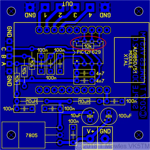
In older versions of the software for this project, it was necessary to re-program the PIC if you wanted to do another calibration. Well, I've been fiddling yet again and come up with an option that means you can re-calibrate to your hearts content without having to re-program the PIC. It does need a minor pcb mod though and the AD9850/51 module needs to be socketed so it can be removed for part of the procedure. Firstly the pcb mod - you need to fit a 10k resistor between pins 8 & 5 of the PIC, see below. It can easily be done under the pcb.
Next, you will need to make up a little wire jumper lead to connect between the two points shown below in orange (this not a permanent jumper, it is only used during the reset procedure).
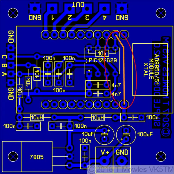
Program your PIC with the software in the downloads section. OK, now on to doing the reset procedure:- 1: With everything powered off, remove the DDS module. 2: Fit the temporary jumper as in the pic above. 3: Power up, leave for a couple of seconds and power down. 4: Remove the temporary jumper, refit the DDS module and carry on as per normal. You can now do another calibration run - no re-programming required. Each time you want to do another calibration, all you need to do is repeat the above procedure.
Calculating and entering different frequencies
For those with Windows systems, it is easier to use the upgraded scientific calculator available for download (in "Programmer" mode). Users of other operating system (or those that don't want to download the calculator), will need a decimal to hex converter program of some sort (unless you are lucky enough to be able to do it in your head). In the 2017_DDS_VFO_V2-4.asm file, starting at line 108, are several 'EQU' statements for upper frequency limit, lower frequency limit, default start frequency and calibrate frequency. I will use the values currently in the file to show you how to get the numbers. The following sequence applies to all four of the 'EQU' sections (with different numbers of course). Firstly, enter the dec number 5500000 (5.5 million) into your dec to hex calculator/program (I'm not going to tell you how to work your calculator/program, you need to work that out). The HEX number will be 53EC60 Now break this number down into groups of 2, starting from the right hand side:- 53 EC 60 The right hand number is the least significant byte, so you enter 0x60 into the line that says, funnily enough, least significant byte. Enter 0xEC in the next line up and 0x53 into the line above that. The '0x' tells the MPlab compiler that the number is in HEX format. So, where is the most significant byte? Well, in this case, it is 00, because 5500000 only converts to the three bytes just shown. So, if your calculation only gives you three nice even groups of two numbers, the most significant byte will be 0x00. Lets do another one that doesn't give you three nice even groups of two numbers. Enter 17000000 (17 million) into your calculator/program. It should come back with the HEX number of 1036640. Breaking that down into groups of 2 as before gives you: 1 03 66 40. Not so nice even groups of two numbers plus an odd one. To fix that, you put a '0' in front of the 1 to get 01 03 66 40. Because nought is nought (or zero is zero), it has no effect on the calculated value, so you can enter the numbers as before, but the most significant byte will now be 01. Don't forget to put 0x in front of your numbers, otherwise, strange things will happen. Using the AD9850 or '51 modules, the most significant byte will not be any more than 03 hex (which puts you upwards of 50MHz).
LED Indicator Add-on
Note:- it is NOT possible to apply this add-on to the original version of this project. Here is a little add-on that will enable the Simple VFO to indicate the selected step size via 3 LED's. Can be expanded to a total of 9 LED's if you feel so inclined to modify the software.
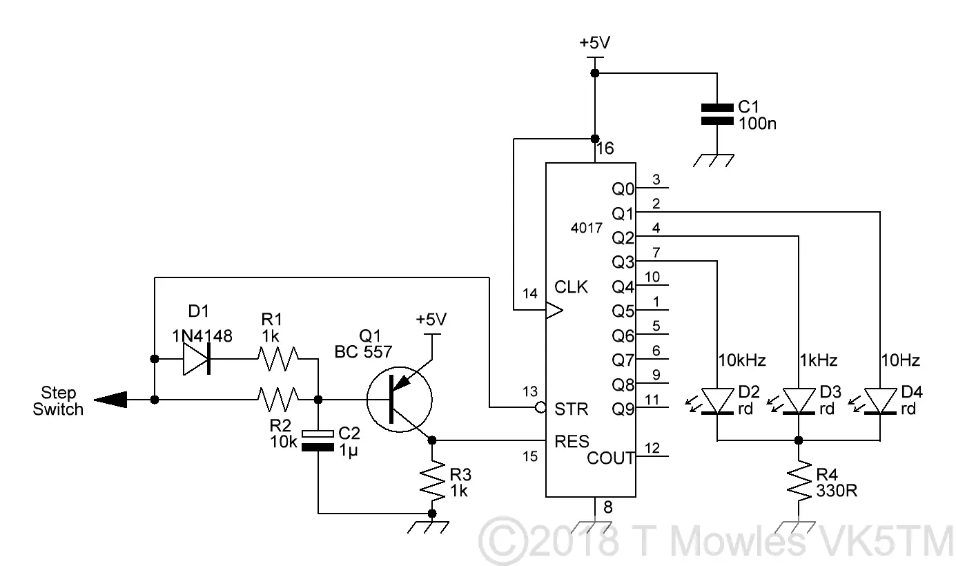
The theory of operation, is that the step switch input, which is held high, will hold Q1 off, thus enabling the 4017 (the reset input is held low by the 1k resistor). Pressing the step switch and pulling the line low causes Q1 to turn on, taking the reset pin high and resetting the 4017. In software, after the step switch has been released, the pin (A on the VFO schematic) is then made an output and after a short delay, a number of short pulses, according to the step size selected (1 for 10Hz, 2 for 1kHz and 3 for 10kHz), are sent to the 4017 to clock the outputs of the 4017 and light the appropriate LED. The combination of R2/C2, having a time constant of ~10mS, prevents Q1 reacting to these short (100uS) pulses. D1 & R1 enable C2 to charge quickly whenever the step switch input goes high. All of this happens fast enough to be transparent to the user, I haven't been able to push the step switch fast enough to upset anything. With so few components, this can easily be constructed on a small piece of stripboard. This is the prototype, made up on a bit of matrix board. Ignore the yellow LED, I used it to indicate when the 4017 was in reset during troubleshooting.
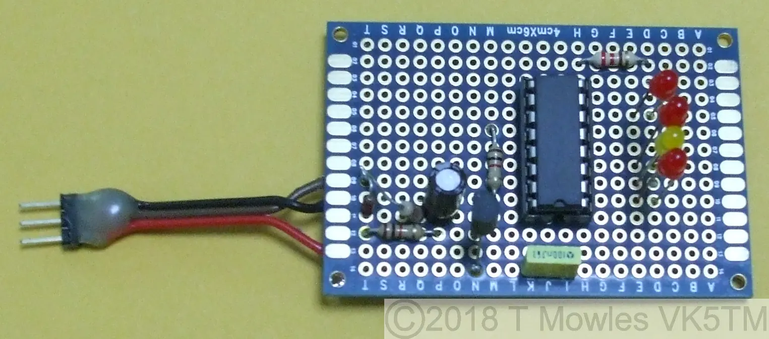
The software - updated to version 2.4 - is a universal version and works with this add-on. You may notice a slight flicker from one or other of the LED's when pushing the step switch, that is the 4017 reverting to reset mode.
Downloads
These files are provided free for personal use ONLY. I retain copyright on all works published on this website (unless otherwise specified). These files, or any derivative of them, may NOT be used in any commercial or profit making enterprise of any kind.
Code updated to version '2.4' - fixed calibration reset routine error and updated encoder routine. This is a universal version and covers all the options above. Note the resistor from pin 5 of the PIC to GND must be fitted. You will need to do the 'Calibration reset hardware modification' regardless of whether you will be using this function or not. Version 2.4 also includes the LED indicator option and if you are not using this option, you can just ignore it, everything will work just fine. (Right click and 'Save as..' or what ever is required by your browser) 2017_DDS_VFO_V2-4.asm The ASM file for the VFO. It is set to AD9850 by default. Instructions in the file to change it to AD9851. Default VFO range 5 - 5.5MHz. 2017_DDS_VFO_V2-4.hex AD9850 hex file. Using a 12F675 I have been asked if the above files will work with a 12F675. Short answer, with some changes, yes. 2017_DDS_VFO_V2-4_12F675.asm 12F675 version of 2017_DDS_VFO_V2-4.asm. 2017_DDS_VFO_V2-4_12F675.HEX 12F675 version of 2017_DDS_VFO_V2-4.hex.
PM5326 Software
Software for the Philips PM5326 DDS mod as described elsewhere on this site. April 2022 As I have now run out of 12F629's, I have redone the code for the 12F1840. Both sets of files are available for download - operationally they are exactly the same. PM5326_2021_629.asm The ASM file for the PM5326 mod - it uses an AD9850 only - 12F629 version. PM5326_2021_629.HEX The HEX file for the PM5326 mod - 12F629 version. PM5326_2021_1840.asm The ASM file for the PM5326 mod - it uses an AD9850 only - 12F1840 version. PM5326_2021_1840.HEX The HEX file for the PM5326 mod - 12F1840 version.
RE-PROGRAMMING PROBLEMS: I have had reports of people not being able to re-program their PIC's. This is a programmer problem. Some programmers do not explicitly follow the programming protocols of these chips and apply both Vdd (5v supply) and Vpp (programming voltage) at the same time. When these voltages are applied in this fashion, the PIC starts to run the program and the programmer is unable to capture the pins necessary to perform the programming. (Also, some programmers, in "Erase" mode will wipe out the "OSCCAL" value in the chip which will also cause problems. Do an internet search on Osscal calibration and read up on fixing this problem). There are several solutions to the re-programming problem: 1/ Look for a menu option in your programming software to see if there is an "Assert Vpp first" or similar worded option. 2/ If that option is not available, you may be able to modify your programmer by fitting a 47 - 100 ohm resistor in series with the 5v line to the PIC and adding a 47uf cap to ground at the 5v pin of the PIC. DO NOT try this if you are not sure or don't have the requiste skills to do it. Note that I have not tried this, but it is mentioned as an option on several forums dealing with PIC's and programming. 3/ Borrow or buy a programmer that is capable of asserting Vpp first. The PicKit 2 & 3 are two I know of that can do this and I have confirmed that they do work to rescue the PIC.
